
14 July 2026
Retro Computing: No two clocks alike
by Roland van Straten
Retro Computing is going back in time for fun and fundamental technology. It won’t solve problems better than with today’s computers, but it is where it all started.
No Two Clocks Alike
When using retro CPU’s and MPU’s today there is always a need for a crystal or an oscillator for the microprocessor clock and a lower frequency clock for baudrates.
The modern type of microcontrollers like ARM Cortex have complex timers and are well equipped to generate these kind of clocks. Also, the chips itself are small enough to be added like one would add an oscillator to a PCB.
Programming For Hardware
This blog article is bringing together the clock generation of processor and baudrate for an UART. It is based on a STM32F407. There is a code example to derive the different clocks. In this example project we use PE9 (PA8) and PE11 (PA9) to generate the different signals like Φ1, Φ2, E, Q.
PA8/PA9 are not usable if USB is used on the STM32F407 as PA9 is used by the USB interface. Therefor the alternative set PE9/PE11 is used.
Timing
Not all timing requirements are exact, but the difference is little enough for it to work without a problem.
Other Functions Too
Besides the clock generation, the use of the STM32 also opens up more utility functions around the retro-processor. Think about debouncing RESET and INTERRUPT switches, single stepping, speed change, etc.
Already people are using the RP2040, ESP32, AVR for things like video generation, etc. Today’s hardware is fast enough to do it, without the need of an FPGA.
How About Reset
A good addition would be to have reset also be handled by the STM32. In that way the reset can be released when the clock is stable.
Retro Processors
| CPU | Clock input | What to connect | PE9 | PE11 |
|---|---|---|---|---|
| MC6800 | Φ1 + Φ2 external | Non-overlapping two-phase | Φ1 |
Φ2 |
| MC6802 | EXTAL (single) | Single clock, XTAL→GND | CLK |
nc |
| MC6809 | EXTAL (single,×4) | 4 MHz for 1 MHz bus | CLK |
nc |
| MC6809E | E + Q external | Quadrature (Q leads E by 90°) | E |
Q |
| Z80 | CLK (single) | Single clock | CLK |
nc |
| 6502 | Φ0 (single) | Single clock, Φ1/Φ2 are outputs | CLK |
nc |
| 65C02 | Φ0 (single) | Single clock | CLK |
nc |
Logic Levels Have Changed
The retro chips use 5V as VCC. Some chips use higher positive voltages and some old memory chip need a negative voltage too.
The STM32F407 has a set of 5V-tolerant pins, but it would be wise to buffer the signals. So using a 74HCT244 is a save choice opening up the use of more different microcontrollers.
Clockgenerator using MicroPython
Using micropython is possible as the clocks will be generated by the timer hardware of the chip. For better readability and understanding, but even more so, hacking through the REPL makes this an interesting choice. You can easily lower the clock frequency just by typing a few commands!
MC6800
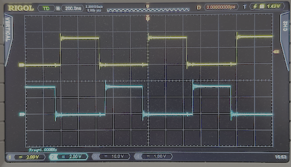
The MC6800 needs non-overlapping clocks. To solve this with the timer, the PWM is set to CENTER mode.
MC6809E
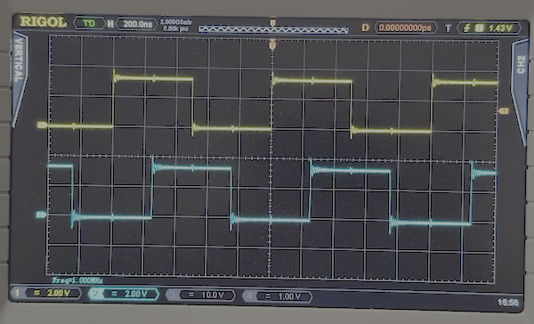
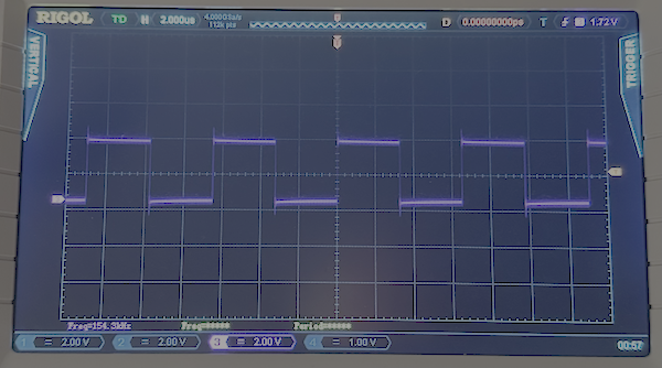
The MC6809E expects E and Q clock that are 180° different (inverted), but the Q clock must lead the E clock by 90°.
Z80
6502
Baudrate
Retro Clock MicroPython Code
The code is written in MicroPython. This works as the clock generation is using timers and as such are software independent. The use of MicroPython makes the code easy readable, give instant gratification and no compile cycles as with C or C++.
The module can be run as the main module or indirect like:
    import retro_clock as clk
    clk.init('mc6809e_1m', 115200)
    clk.info()
    clk.select_baud(9600)
The info() function will show the state of the clock generators:
>>> clk.info()
CPU:   8,000,000 Hz  ARR=20 CCR=10 (single clock)
Baud:    115,384 x 16 = 1,846,153 Hz  ARR=90
Following is the listing of the program to set both processor and baudrate (x16) clocks.
# retro_clock.py
#
# STM32F407 MicroPython
#
# PE9 /PA8 = TIM1 CH1  Phi1 / Q / CLK / EXTAL  (always driven)
# PE11/PA9 = TIM1 CH2  Phi2 / E                (two-output CPUs only)
# PA2      = TIM9 CH1  baud × 16 clock
#
# Requires MicroPython with pyb (standard STM32F4 build, 168 MHz)
# Buffer outputs through 74HCT244 for 5V CPUs.
#
# ── Clock architecture per CPU ──────────────────────────────────
#
# MC6800          PE9=Phi1, PE11=Phi2
#   Requires external two-phase non-overlapping clock.
#   About 40% duty each with dead-time gap between phases.
#
# MC6802          PE9=EXTAL only
#   Built-in oscillator. Single clock in, XTAL pin → GND.
#
# MC6809          PE9=EXTAL only  (feed 4× bus frequency)
#   Built-in oscillator divided by 4 for 1MHz bus, XTAL → GND.
#
# MC6809E         PE9=Q, PE11=E
#   No internal oscillator. Q and E externally supplied.
#   Q and E are complementary 50% clocks: Q leads E by half a period.
#   They transition simultaneously — no dead-time gap required.
#
#   Q=PWM mode 1, E=PWM_INVERTED, same CCR value.
#
# Z80             PE9=CLK only
#
# 6502 / 65C02    PE9=Phi0 only  (Phi1/Phi2 on 6502 are OUTPUTS, not inputs)
#

import pyb
import stm

# ── Configuration tables ─────────────────────────────────────────
#
# Format: (mode, period_ticks, ccr1, ccr2_or_None, ch2_mode)
#   mode         : _UP, _CENTER, or _QUAD
#   period_ticks : full waveform period in 168 MHz timer ticks
#                  _UP:     ARR = period_ticks - 1
#                  _CENTER: ARR = period_ticks // 2   (counter 0->ARR->0)
#                  _QUAD:   ARR = period_ticks//2 - 1 (toggle halves the rate)
#   ccr1         : CH1 compare value
#   ccr2         : CH2 compare value, or None for single-output CPUs
#   ch2_mode     : pyb.Timer.PWM / pyb.Timer.PWM_INVERTED / None (unused in _QUAD)
#
# PWM mode 1 (Timer.PWM):          HIGH while CNT < CCR
# PWM mode 2 (Timer.PWM_INVERTED): LOW  while CNT < CCR, HIGH while CNT >= CCR
#
# Notes on 6800
# -------------
# Phi1/Phi2 must be non-overlapping: a dead band at BOTH handovers.
# In _UP (edge-aligned) mode two edges are welded to the rollover event
# (CH1 always rises at CNT=0, CH2/PWM_INVERTED always falls there), so
# only the mid-period handover can be gapped. In _CENTER mode the counter
# runs 0->ARR->0 and each output toggles at its CCR going up AND coming
# down: both handovers get the same (CCR2-CCR1)-tick gap.
#
# mc6800_1m (ARR=84, CCR1=37, CCR2=48), one 168-tick period:
#   Phi1 HIGH 73t=434ns | dead 11t=65ns | Phi2 HIGH 73t=434ns | dead 11t=65ns
#   (6800 spec: PWphiH >= 400 ns)
#
# Notes on 6809E
# --------------
# A real 6809E drives Q leading E by 90 deg (quadrature), not 180.
# Neither _UP nor _CENTER can place two 50% clocks 90 deg apart, so
# _QUAD uses output-compare TOGGLE mode instead: the counter period is
# HALF the bus period, each channel flips its pin every time CNT passes
# its CCR, giving an exactly-50% clock whose phase IS its CCR value.
#   ccr2 - ccr1 = quarter of the bus period  ->  Q leads E by 90 deg.
#
# Toggle mode is polarity-ambiguous (a channel that arms one half-period
# late runs inverted, making Q LAG). _setup_quad() makes it deterministic:
# arm both channels FORCED_INACTIVE (pins low), stop the counter, zero
# CNT, switch both OCxM fields to toggle, then start. First toggle on
# each pin is therefore rising, from a known CNT=0.
#
# mc6809e_1m (ARR=83, CCR1=21, CCR2=63):
#   Q rises t=21, falls t=105; E rises t=63, falls t=147 (168t period)
#   both exactly 50% (500 ns high), E lags Q by 42t = 250 ns = 90 deg

_PWM     = pyb.Timer.PWM
_PWM_INV = pyb.Timer.PWM_INVERTED
_UP      = pyb.Timer.UP
_CENTER  = pyb.Timer.CENTER
_QUAD    = 'QUAD'          # our marker: OC toggle mode, 90 deg pair

_CPU_CONFIGS = {
    # name          mode     period  ccr1  ccr2  ch2_mode
    # Two-outputs
    'mc6800_1m':  ( _CENTER, 168,    37,   48,  _PWM_INV ),  # Phi1+Phi2, 65ns dead band both sides
    'mc6809e_1m': ( _QUAD,   168,    21,   63,  None     ),  # Q+E quadrature, Q leads 90deg, 1MHz
    'mc6809e_2m': ( _QUAD,    84,    10,   31,  None     ),  # Q+E quadrature, Q leads 90deg, 2MHz
    # Single-output
    'mc6802_1m':  ( _UP,     168,    84, None,  None     ),  # EXTAL 1MHz (50% on PE9)
    'mc6802_4m':  ( _UP,      42,    21, None,  None     ),  # EXTAL 4MHz
    'mc6809_1m':  ( _UP,      42,    21, None,  None     ),  # EXTAL 4MHz -> 1MHz bus (/4)
    'mc6809_2m':  ( _UP,      21,    10, None,  None     ),  # EXTAL 8MHz -> 2MHz bus (/4)
    'z80_8m':     ( _UP,      21,    10, None,  None     ),  # CLK 8MHz exact
    'z80_7m3':    ( _UP,      23,    11, None,  None     ),  # CLK 7.304MHz (~7.3728, -0.93%)
    '6502_1m':    ( _UP,     168,    84, None,  None     ),  # Phi0 1MHz
    '6502_2m':    ( _UP,      84,    42, None,  None     ),  # Phi0 2MHz
}

_BAUD_CONFIGS = {
    # baud   period  ccr    error
    115200: (  91,   45 ),  # +1603 ppm
     57600: ( 182,   91 ),  # +1603 ppm
     38400: ( 273,  136 ),  # +1603 ppm
     19200: ( 547,  273 ),  # - 229 ppm
      9600: (1094,  547 ),  # - 229 ppm
      4800: (2188, 1094 ),  # - 229 ppm
      2400: (4375, 2187 ),  # exact
      1200: (8750, 4375 ),  # exact
}


_tim1     = None
_tim9     = None
_ch1      = None
_ch2      = None
_ch_baud  = None
_cpu_freq = 0      # actual output frequency, set by _setup_cpu()
_cpu_mode = None   # _UP / _CENTER / _QUAD, for info()


def init(cpu='z80_8m', baud=115200):
    """
    Initialise CPU clock and baud rate clock.

    cpu  : string key from _CPU_CONFIGS, e.g. 'mc6800_1m', 'z80_8m'
    baud : integer, e.g. 115200, 9600

    Example:
        import retro_clock as clk
        clk.init('mc6809e_1m', 115200)
        clk.info()
    """
    _setup_cpu(cpu)
    _setup_baud(baud)

def select_cpu(cpu):
    """Switch CPU clock. See _CPU_CONFIGS keys for options."""
    _setup_cpu(cpu)

def select_baud(baud):
    """Switch baud rate clock. baud: 115200/57600/38400/19200/9600/4800/2400/1200"""
    _setup_baud(baud)

def stop_cpu():
    """Stop CPU clock outputs (PE9/PE11 go low)."""
    global _tim1
    if _tim1:
        _tim1.deinit()
        _tim1 = None

def stop_baud():
    """Stop baud clock output (PA2 goes low)."""
    global _tim9
    if _tim9:
        _tim9.deinit()
        _tim9 = None

def _setup_cpu(cpu):
    global _tim1, _ch1, _ch2, _cpu_freq, _cpu_mode

    if cpu not in _CPU_CONFIGS:
        raise ValueError("Unknown CPU '{}'. Options: {}".format(
            cpu, sorted(_CPU_CONFIGS.keys())))

    mode, period, ccr1, ccr2, ch2_mode = _CPU_CONFIGS[cpu]

    if _tim1:
        _tim1.deinit()
        _tim1 = None

    _cpu_freq = 168_000_000 // period
    _cpu_mode = mode

    if mode == _QUAD:
        _setup_quad(period, ccr1, ccr2)
        return

    # _UP:     counter 0..ARR then wraps  -> ARR = period - 1
    # _CENTER: counter 0 -> ARR -> 0      -> ARR = period // 2
    arr = (period // 2) if mode == _CENTER else (period - 1)

    _tim1 = pyb.Timer(1, prescaler=0, period=arr, mode=mode)

    # CH1: always PWM mode 1
    _ch1 = _tim1.channel(1, _PWM, pin=pyb.Pin.cpu.E9, pulse_width=ccr1)

    if ccr2 is not None:
        # Two-output CPU: CH2 on PE11
        # PWM_INVERTED: output LOW while CNT < ccr2, HIGH while CNT >= ccr2
        _ch2 = _tim1.channel(2, ch2_mode, pin=pyb.Pin.cpu.E11, pulse_width=ccr2)
    else:
        _ch2 = None

def _setup_quad(period, ccr1, ccr2):
    """
    6809E Q/E quadrature via OC toggle mode.

    Counter period = period//2 ticks; each channel toggles its pin at
    CNT == CCR, so both pins output exactly-50% clocks at the full bus
    period, phase-shifted by (ccr2 - ccr1) ticks. The forced-inactive ->
    stop -> CNT=0 -> toggle -> start : first edge on each pin is rising,
    so Q (CH1, lower CCR) leads E by 90 deg.
    """
    global _tim1, _ch1, _ch2

    half = period // 2
    _tim1 = pyb.Timer(1, prescaler=0, period=half - 1)

    # Arm both channels with outputs FORCED low. This sets up the GPIO
    # alternate function, CCR values, CCxE and MOE, but no edges yet.
    _ch1 = _tim1.channel(1, pyb.Timer.OC_FORCED_INACTIVE,
                         pin=pyb.Pin.cpu.E9,  compare=ccr1)
    _ch2 = _tim1.channel(2, pyb.Timer.OC_FORCED_INACTIVE,
                         pin=pyb.Pin.cpu.E11, compare=ccr2)

    base = stm.TIM1
    stm.mem32[base + stm.TIM_CR1] &= ~1          # CEN=0: stop counter
    stm.mem32[base + stm.TIM_CNT]  = 0           # known phase, both pins low

    # OC1M (CCMR1 bits 6:4) and OC2M (bits 14:12): forced-inactive -> toggle (011)
    m = stm.mem32[base + stm.TIM_CCMR1]
    m = (m & ~((7 << 4) | (7 << 12))) | (3 << 4) | (3 << 12)
    stm.mem32[base + stm.TIM_CCMR1] = m

    stm.mem32[base + stm.TIM_CR1] |= 1           # CEN=1: run

def _setup_baud(baud):
    global _tim9, _ch_baud

    if baud not in _BAUD_CONFIGS:
        raise ValueError("Unknown baud {}. Options: {}".format(
            baud, sorted(_BAUD_CONFIGS.keys(), reverse=True)))

    period, ccr = _BAUD_CONFIGS[baud]

    if _tim9:
        _tim9.deinit()
        _tim9 = None

    _tim9 = pyb.Timer(9, prescaler=0, period=period - 1)
    _ch_baud = _tim9.channel(1, _PWM, pin=pyb.Pin.cpu.A2, pulse_width=ccr)


def info():
    """Print current configuration to REPL."""
    if _tim1:
        arr = _tim1.period()
        c1  = _ch1.compare()
        if _ch2:
            c2  = _ch2.compare()
            tag = "Q leads E 90deg" if _cpu_mode == _QUAD else "two-phase"
            print("CPU:  {:>10,} Hz  ARR={} CCR1={} CCR2={} ({})".format(
                _cpu_freq, arr, c1, c2, tag))
        else:
            print("CPU:  {:>10,} Hz  ARR={} CCR={} (single clock)".format(
                _cpu_freq, arr, c1))
    else:
        print("CPU:  stopped")

    if _tim9:
        arr  = _tim9.period()
        xf   = 168_000_000 // (arr + 1)
        print("Baud: {:>10,} x 16 = {:,} Hz  ARR={}".format(xf // 16, xf, arr))
    else:
        print("Baud: stopped")


def print_help():
    print("""
Quick reference ──────────────────────────────────────────────

 CPU targets:
   'mc6800_1m'   1 MHz   Phi1+Phi2  non-overlapping, 65 ns dead band both handovers
   'mc6809e_1m'  1 MHz   Q+E        quadrature 50%, Q leads E by 90 deg
   'mc6809e_2m'  2 MHz   Q+E        quadrature 50%, Q leads E by 90 deg
   'mc6802_1m'   1 MHz   EXTAL      single clock, internal osc takes over
   'mc6802_4m'   4 MHz   EXTAL      single clock
   'mc6809_1m'   4 MHz   EXTAL      -> 1 MHz bus (chip divides by 4 internally)
   'mc6809_2m'   8 MHz   EXTAL      -> 2 MHz bus (chip divides by 4 internally)
   'z80_8m'      8 MHz   CLK        exact
   'z80_7m3'  7.304 MHz  CLK        ~7.3728 MHz, -0.93%
   '6502_1m'     1 MHz   Phi0       single clock (6502 Phi1/Phi2 are OUTPUTS)
   '6502_2m'     2 MHz   Phi0       single clock

 Baud rates: 115200 57600 38400 19200 9600 4800 2400 1200
 All within +/-1603 ppm of target (UART tolerance = +/-20000 ppm)

 print_help()
 select_cpu()
 stop_cpu()
 select_baud()
 stop_baud()
 info()
 init()
""")

if __name__ == "__main__":
    print_info()

    init()
    info()